How to Use the Stabilization Receiver (II)
4. Stabilization Receiver Six-Side Calibration
Each stabilization receiver has undergone six-side calibration before leaving the factory and can be used directly without calibration upon receipt. If the stabilization function of the receiver malfunctions or fails, it will be necessary to recalibrate the receiver. The calibration procedure is as follows:
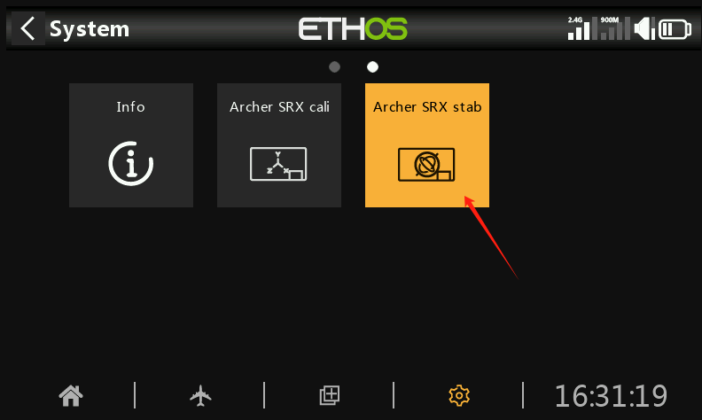
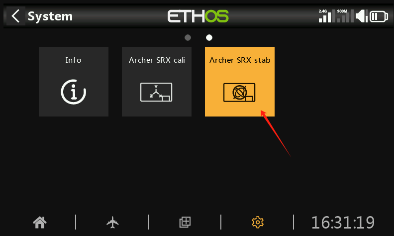
① Enter the SRX stab icon
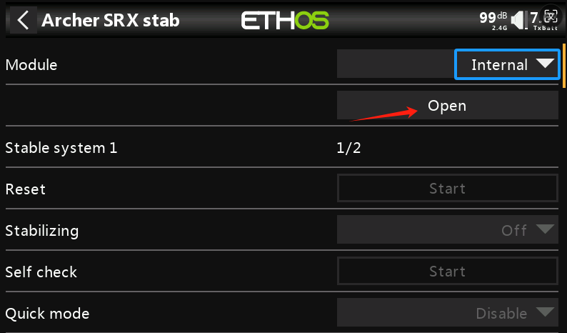
①-①. First, select the Module RF Mode. If the receiver is bound using the internal RF module of the transmitter, choose Internal; if bound with an external high-frequency module, choose External. After selecting the RF mode, click Open, then exit the menu.
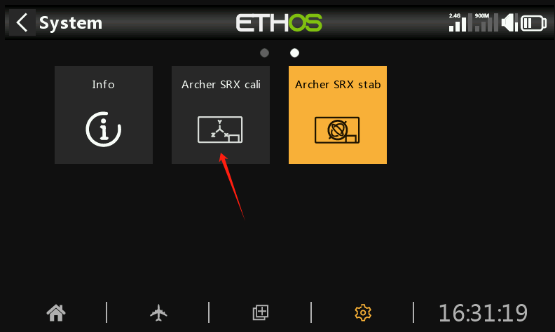
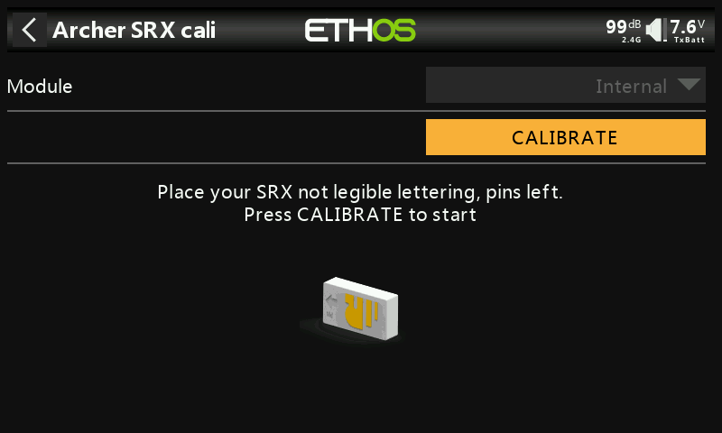
② Enter the SRX Cali icon
②-① As in steps 1-1, select the Module RF Mode.
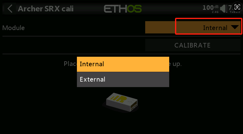
②-② After selecting the RF mode, position the receiver as shown in the (with the logo facing up and the pins to the right) for the first side calibration. Click CALIBRATE to complete the calibration for the first side.
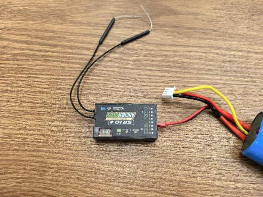
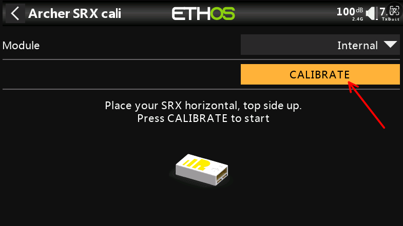
②-③ Position the receiver as shown in the diagram (with the logo facing down and the pins to the right) for the second side calibration. Click CALIBRATE to complete the second side calibration.
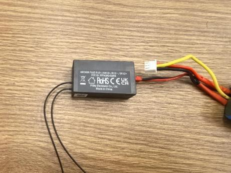
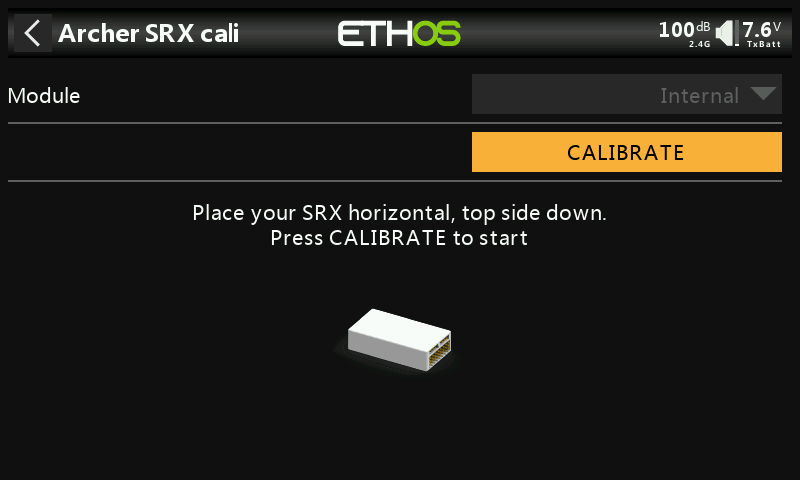
②-④ Position the receiver as shown in the diagram (with the logo facing you and the pins pointing upward) for the third side calibration. Click CALIBRATE to complete the third side calibration.
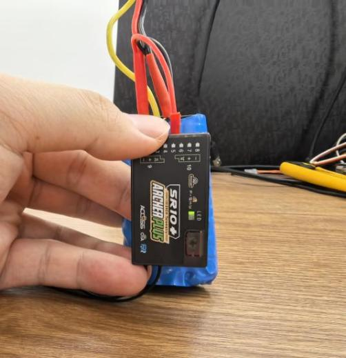
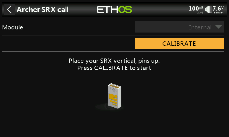
②-⑤ Position the receiver as shown in the diagram (with the logo facing you and the pins pointing downward) for the fourth side calibration. Click CALIBRATE to complete the fourth side calibration.
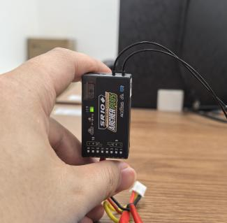
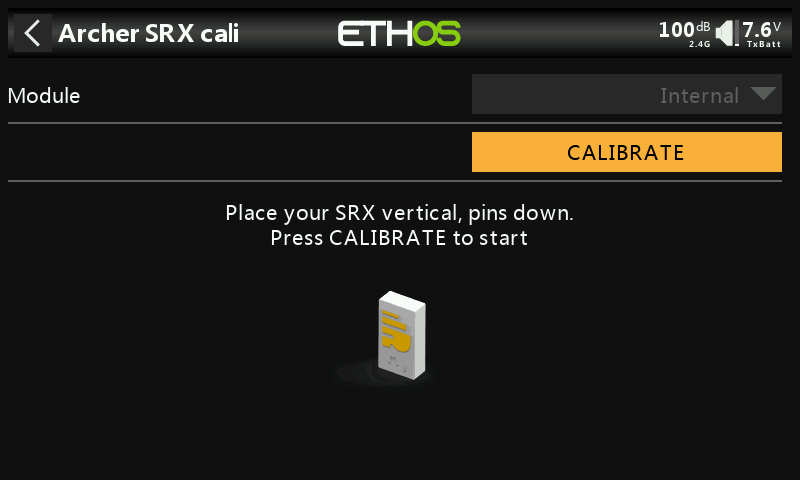
②-⑥ Position the receiver as shown in the diagram (with the logo facing you and the pins to the right) for the fifth side calibration. Click CALIBRATE to complete the fifth side calibration.
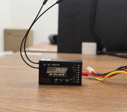
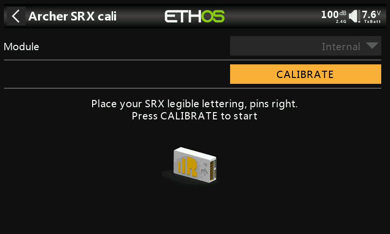
②-⑦ Position the receiver as shown in the diagram (with the logo facing you and the pins to the left) for the sixth side calibration. Click CALIBRATE to complete the sixth side calibration.
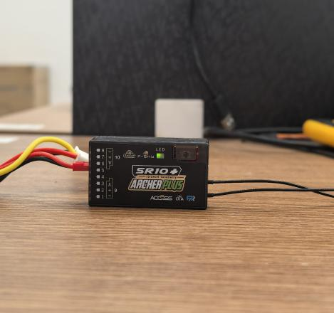
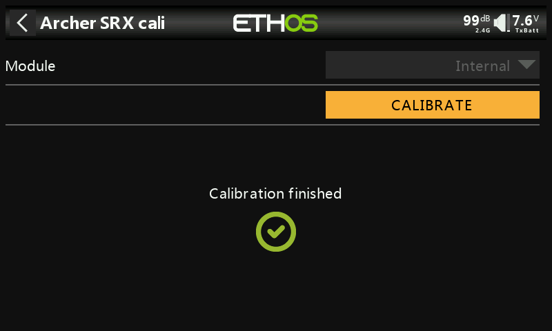
②-⑧ Calibration complete.
5. Stabilization Parameter Adjustment
① Click the SRX stab icon.
② The stabilization parameter adjustment interface consists of two pages.
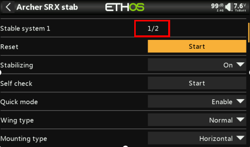
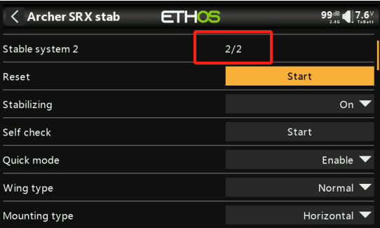
②-① Press the middle button on the left side of the transmitter to switch between pages. Short press to move to the next page, and long press to go back to the previous page.
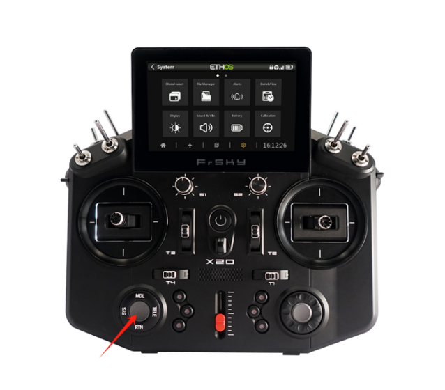
②-② The first page allows you to enable/disable the first set of stabilization channels (CH1-6), while the second page allows you to enable/disable the second set of stabilization channels (CH7-11).
Note 1: The stabilization settings on both pages are independent. If you need to perform a Self-check calibration, each page must be calibrated separately.
Note 2: If only CH1-6 is being used and CH7-11 is not, there's no need to set stabilization for CH7-11 on the second page.
③ The following two photos show the stabilization parameter adjustment contents for the first and second pages.


Stabilization Parameter Adjustment Explanation:
- Module: If the receiver is bound using the internal RF module of the transmitter, select Internal; if bound with an external high-frequency module, select External, then click ‘OPEN’ to access the stabilization parameter adjustment page.
- Reset: Clicking ‘Start’ will reset the stabilization parameter settings on both pages to their factory defaults. Please proceed with caution.
- Stabilization Function: Toggle stabilization on (enable) or off (disable).
- Self-Check: Click ‘Start’ to begin calibrating the stick travel for each channel. This is typically used before the first flight or when the stick channel travel behaves abnormally in stabilization mode. The steps are as follows:
a. Place the aircraft in a level position, set the throttle to the lowest position, and leave the other channels centered.
b. Select Self Check and click ‘Start’. The blue LED will light up. When the blue LED starts blinking, immediately move the three stick channels (except the throttle) to their full travel range to calibrate the maximum travel (excluding the throttle).
c. After completing the stick movements, release all sticks. When the blue LED stops blinking, the receiver's servos will move back and forth, indicating that the calibration is complete.
- Quick Mode: The stabilization function has two flight modes: Enable (Quick Mode) and Disable (Traditional Mode).
a. In Quick Mode, there are only three modes: Manual (stabilization off), Stabilized, and Auto-Level. This mode is switched via CH14, as shown in the diagram (for traditional fixed-wing, delta-wing, and V-tail fixed-wing).

b. Traditional Mode includes five modes: Stabilized, Auto-Level, Hover, Knife-edge, and Manual (stabilization off). This mode is switched using the CH14 & CH15 combination, as shown in the diagram (only applicable to traditional fixed-wing).

c. Traditional Mode for delta-wing and V-tail fixed-wing includes three modes: Stabilized, Auto-Level, and Manual (stabilization off). This mode is switched via CH14, as shown in the diagram.

- Wing Type:
Options: Normal (Traditional Fixed-Wing), Delta (Delta-Wing), VTail (V-Tail Fixed-Wing)
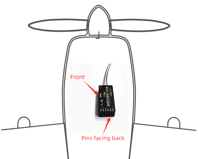
- Installation Orientation: Refer to the picture for receiver installation options:
Horizontal (Logo facing up, pins facing back)、Horizontal reverse (Logo facing down, pins facing back)、Vertical (Logo facing left, pins facing back)、Vertical reverse (Logo facing right, pins facing back)
- CH1-6 Mode on Page 1 & CH7-11 Mode on Page 2, you can choose to use the self-stabilizing function of the corresponding channel or customize (non-self-stabilizing), as shown in the picture:
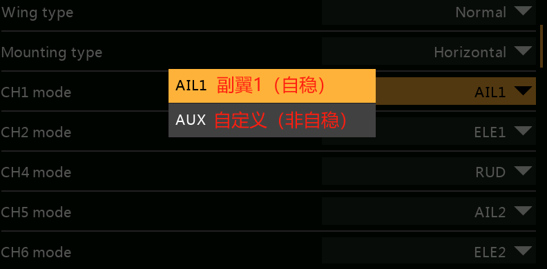
Note: When a channel is set to AUX, it becomes a regular channel without stabilization and can be used for devices like flaps or landing gear.
- Stick (Aileron, Elevator, Rudder) Reversal: In stabilization mode, the channel travel can be reversed, On (reverse on), Off (reverse off)
- Stabilization Sensitivity: Adjustment of sensitivity in stabilization mode.
- Auto-Level Sensitivity: Adjustment of sensitivity in auto-level mode.
- Tilt/Pitch Angle Limit: No effect from 0-10°, with a maximum setting of 80°. If set to 80°, the tilt angle at full stick deflection will be 80°. This function only works in auto-level mode (technically, the angle limit function replaces the auto-level mode function).
- Stick Forward/Reverse Travel Priority: as shown in the picture:
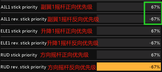
If the forward travel value of aileron 1 is set to 67%, then within 67% of the forward travel on the aileron 1 channel, it will be in stabilization mode. If it exceeds 67%, it will switch to manual mode.
The same applies to reverse travel. If set to -67%, within -67% of reverse travel, it will be in stabilization mode, and below -67% it will switch to manual mode.
Note 1: This function works in stabilization, auto-level, hover, and knife-edge modes.
Note 2: If the Tilt/Pitch Angle Limit is enabled, this function will not work in auto-level mode.
Note 3: The Tilt Angle Limit corresponds to Aileron and Rudder Priority; the Pitch Angle Limit corresponds to Elevator Priority.
6. Aircraft Stabilization Function Tuning Process:
(On the ground) First, tune the receiver in “Auto-Level Mode” (set all trims to 0, and do not adjust the trims yet—just check if the control surfaces are correct and if they reverse when moving the sticks. If any surfaces are reversed, correct them directly on the parameter adjustment page, no need to level them). After tuning, switch to Manual Mode. If any surfaces are unlevel within a 50us range, use the trim buttons to adjust. If the deviation exceeds 50us, it must be adjusted mechanically. Afterward, perform a Self Check (the self-check applies to all modes). Finally, conduct a test flight in Auto-Level Mode to check for any unlevel control surfaces. If there are any, adjust the Auto-Level Trim in the parameter adjustment script. Once this is done, the process is complete.
Note: Before using the new self-stabilization script, make sure to delete the previous script, as the two cannot coexist.
